You are using an out of date browser. It may not display this or other websites correctly.
You should upgrade or use an alternative browser.
You should upgrade or use an alternative browser.
Engine cut out as I was going along the Mway!!
- Thread starter Sprackers
- Start date
iMacThere4iAm
Tom Long
- Messages
- 750
- Location
- Morecambe
The condenser is the small cylinder bolted to the side of the distributor, as shown in this photo.

However electronic ignition usually replaces the condenser and sometimes the points, so you might not have one.
My electronic ignition has been nothing but reliable, but if you suspect a problem with yours it might be worth putting back the stock points and condenser just to rule it out.
However electronic ignition usually replaces the condenser and sometimes the points, so you might not have one.
My electronic ignition has been nothing but reliable, but if you suspect a problem with yours it might be worth putting back the stock points and condenser just to rule it out.
mojobaby
Enthusiast
- Messages
- 1,320
I think a lot of people, myself included, are following your story with interest, wondering what they would do if it happened to them.
Just to clarify:- if you have electronic ignition and no condenser, do you have points, as per iMac's post? Have you checked your gap as it sounds like the points are closed, or badly pitted.
Also what are the results of your coil test so far?
Hope you sort out your problem soon
I've just checked a few posts on internet and they said that a faulty coil stops making a spark when it gets hot. that's why your car starts again when it cools down.
Last edited:
Sprackers
Enthusiast
- Messages
- 353
- Location
- Tunbridge Wells England
Definitely no condenser anywhere. As regards Points? What are they?
If you are talking about the little silver contacts inside the top of the distributor cap, yes there are 4 of them. Its not them is it.
An overheating coil would explain, perfectly why Christina suddenly cuts out (would it?) then restarts after about a 30 minutes cooling down of the coil.
The problem mainly is that until she breaks down I can’t diagnose where the problem is.
I have to admit from all your valuable advice, it sounds more and more like it’s the coil.
My only worry. Is it easy to change an electronic condenser and coil back to an original coil and condenser?
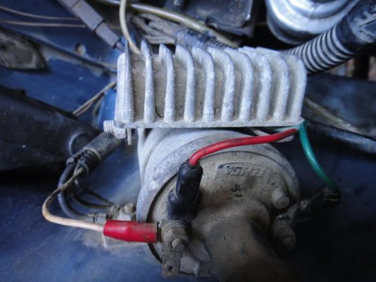
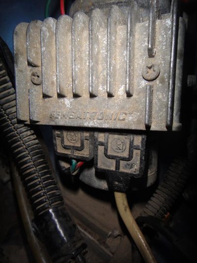
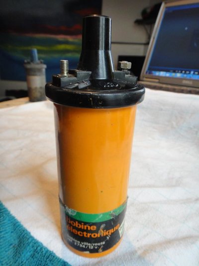
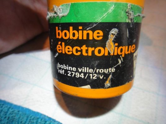
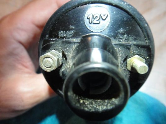
I say that purely because I notice on an original coil there just seems to be two wires emanating from the top and on mine there are 3 wires and a couple of special looking plugs coming from the bottom of the Electronic condenser. (see below)
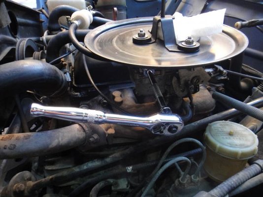
On advice I have, this morning, removed and inspected the little tubular filter in the carburettor. (See below)
Held it up to the light and could easily see through it. Clean to me.
I started her up again this morning . I took 7 times to get her going in short turns (3 seconds) of the ignition key with approximately 15 seconds wait between each turn of the key.
Outside temp here 12ºC.
Once running purrs like a kitten.
The more I think about it, I too think its the coil.
I say that because over the winter to get her started I have been hammering the starting.
ie...turning the key and holding it in the start mode for 5-7 seconds pumping the accelerator. (in the process probably flooding the engine I realise now)
waiting 4 seconds
then again 5-7 seconds turning the starting ignition key.......
4 seconds rest
then again 5-7 seconds
wait
then again 5 -7 seconds.....alomost until the starter grinds to a halt.
That must have put excessive strain on the coil.
iMacThere4iAm
Tom Long
- Messages
- 750
- Location
- Morecambe
It's not them. The points are a spring loaded switch in the distributor that is opened by a four-lobed cam. When the points are opened, the current in the coil primary windings stops, inducing a high voltage pulse in the secondary windings. This article has a nice diagram of the system. You can see the points in the photo I posted yesterday, however I don't recognise the design of your distributor. Hopefully someone else can identify it?Definitely no condenser anywhere. As regards Points? What are they?
If you are talking about the little silver contacts inside the top of the distributor cap, yes there are 4 of them. Its not them is it.
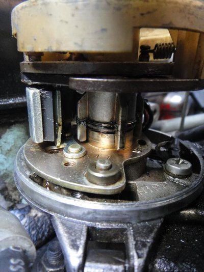
Edit: It looks from the photo above as if the points in your distributor have been replaced by some sort of sensor (on the right).
Edit 2: Found it :P http://club4567.mforos.com/689205/10808794-encendido-femsatronic-nuevo/ Unfortunately I can't find any information in English, and I don't speak Spanish!
It is easy to do but my guess is that the electronic module is OK. It's more likely to fail suddenly and permanently than intermittently and when hot, which like you say does suggest a bad coil.My only worry. Is it easy to change an electronic condenser and coil back to an original coil and condenser?
I say that purely because I notice on an original coil there just seems to be two wires emanating from the top and on mine there are 3 wires and a couple of special looking plugs coming from the bottom of the Electronic condenser. (see below)
Edit 2: I'm starting to suspect that that distributor is a specially made electronic one that can't be converted 'back' to points.
You could try measuring the resistance across your coil. No need to remove it from the car, just disconnect all the wires. According to the internets a value of 0.75 to 0.81 ohms across the primary winding and 10,000 to 11,000 ohms across the secondary winding is OK.
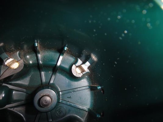
Just seen your pics ,you have a Femsa dizzy with electronic ignition,the cap has a lot of dirt on the terminals from the rotor arm,a Spanish auto electrics company,Renault used there dizzy along with Paris-Rhone and Ducellier,the best one being Ducellier with out a doubt.If you use electronic ignition you need an upgraded coil to cope with increased power.Not really necessary on Quatrelle.and big problem when they go wrong,because you never know what bit is playing up and cant just go out and buy it anyway.My advice would be to find a Ducellier ,new points and condenser,change the coil,and away you go,just my opinion.
I have changed a couple over and the cars went very well.
I have changed a couple over and the cars went very well.
Sprackers
Enthusiast
- Messages
- 353
- Location
- Tunbridge Wells England
IMAC...I speak perfect Spanish He does go onto say that on the box, this starter coil is for a Renault 5, 6 and 7. Not R4. and the bloke has sold it for €170.
I think we have narrowed it down to the Coil and or Electronic condeser.
Im going to change the lot to the simpler and original coil and condeser.
I read in my Haynes that I have to get the right voltage and connector.
I will also clean the contacts inside the distibutor cap, although they look pretty clean to me.
I will report back.
Cornish4
Le Dazzleur
- Messages
- 1,875
- Location
- Falmouth
As well as changing the coil, which doesn't need to be an expensive one, an aftermarket one will do, you also need to replace the distributer as the one you have on your car seems to be a Femsatronic one. In other words you have to start from scratch, as it could be the coil or the module.
A basic Femsa dizzy will do the job, although a Ducellier one is better (easier points adjustment), plus new electronic ignition systems are available for it. A visit to a breakers yard is called for I think. I have a good friend in Brittany who could help you, PM me if you would like his details. Regards Brian.
A basic Femsa dizzy will do the job, although a Ducellier one is better (easier points adjustment), plus new electronic ignition systems are available for it. A visit to a breakers yard is called for I think. I have a good friend in Brittany who could help you, PM me if you would like his details. Regards Brian.
Try Oscaro ,much cheaper and delivered to your door,bosch is ok,i dont trust aftermarket ones in my experiance. A Caisse Auto is what you need for the Dizzy or just get the whole lot second hand,preferably a Ducellier set up.There is also Leboncoin for second hand bits.
montenegro
Enthusiast
- Messages
- 193
I would look on le bon coin [france] or perhaps you have a similar site in spain ? for a replacement distributor [allumage in french] ref for a R1128 is R244 pref ducellier. I just bought a good 2nd hand one for E30.plus a new coil, the coil for electronic ign IS different and should not be used with 'normal' ignition systems.
Sprackers
Enthusiast
- Messages
- 353
- Location
- Tunbridge Wells England
I wish I had read your advice as to where to get a coil before I set off on my expedition to go to the breakers yard.
After cycling for a 1 1/2 hours and then a 30 minute walk to get to the breakers yard (then the same back) where I bought a Bulgarian made second hand coil for €30....
What an idiot I had been done up like a Kipper.
So when I got back and read the advice I thought...Im not having this...So back on the bike and another walk to the breakers yard, where.........RESULT............they gave me my money back.
Back on the bike and back home.
8 hours later I am back where I started.
I have had a look on Oscaro...good deal €27 Bosch + €1 dlv.
Also I have seen another coil just around the corner, on another website but it says its for a Renault 8 not a renault 4?
Whats the difference? they are both 12V, so it should work on my R4? Right?
If so I will go and get it.
iMacThere4iAm
Tom Long
- Messages
- 750
- Location
- Morecambe
I have been reading up about ignition coils. You asked about ballasted vs non-ballasted coils, here's what I understand.
TL;DR version:
If any two coils have the same resistance, you may assume they are interchangeable.
Long version:
When cranking the engine, the starter motor draws so much current that the voltage across the coil is reduced, weakening the spark. A ballast resistor placed in series with the ignition switch (but bypassed by the starter switch) reduces the coil voltage when not cranking so that it is more or less constant all the time. The resistor is usually visibly attached near the coil. A ballasted coil is one which is designed to operate best at reduced voltage (around 9V for example), whereas an unballasted coil is designed to operate at 12V. Some electronic ignition systems use a more sophisticated voltage regulator and are designed to work with a special low-resistance coil, whereas some are designed to work with ordinary unballasted coils.
The only way to tell for sure what type of coil you have in front of you is to measure its primary winding resistance. It will be around 3 Ohm for an unballasted coil, or 1.5 Ohm for a ballasted coil. If it is around 1 Ohm, it is a special coil for an electronic ignition that includes its own voltage regulator chip.
To check if your circuit includes a ballast resistor, with the ignition on, detach the (+) wire from the coil and measure its voltage relative to the chassis. It will be around 12V for an unballasted system, or around 9V for a ballasted system.
Specifics:

On your system, my guess is that:

To use this you will definitely need a circuit diagram to know how it should be wired.
TL;DR version:
If any two coils have the same resistance, you may assume they are interchangeable.
Long version:
When cranking the engine, the starter motor draws so much current that the voltage across the coil is reduced, weakening the spark. A ballast resistor placed in series with the ignition switch (but bypassed by the starter switch) reduces the coil voltage when not cranking so that it is more or less constant all the time. The resistor is usually visibly attached near the coil. A ballasted coil is one which is designed to operate best at reduced voltage (around 9V for example), whereas an unballasted coil is designed to operate at 12V. Some electronic ignition systems use a more sophisticated voltage regulator and are designed to work with a special low-resistance coil, whereas some are designed to work with ordinary unballasted coils.
The only way to tell for sure what type of coil you have in front of you is to measure its primary winding resistance. It will be around 3 Ohm for an unballasted coil, or 1.5 Ohm for a ballasted coil. If it is around 1 Ohm, it is a special coil for an electronic ignition that includes its own voltage regulator chip.
To check if your circuit includes a ballast resistor, with the ignition on, detach the (+) wire from the coil and measure its voltage relative to the chassis. It will be around 12V for an unballasted system, or around 9V for a ballasted system.
Specifics:

On your system, my guess is that:
- The cream(?) wire is +12V from the ignition switch
- The red wire is the power supply to the electronic ignition box
- The green wire is connected to earth via the electronic ignition box which switches it on and off
- The white wire from the electronic ignition box carries the timing signal from a magnetic sensor in your distributor

To use this you will definitely need a circuit diagram to know how it should be wired.
Sprackers
Enthusiast
- Messages
- 353
- Location
- Tunbridge Wells England
iMacThere4iAm
Tom Long
- Messages
- 750
- Location
- Morecambe
Measure the resistance  You can't tell by looking at it.


