Chassis Jig Dimensions
Having mislaid the original notes used to construct the chassis jig I've measured the jig and also the parts used to make the jig. I've compared the measurements with the few dimensions available from the factory workshop manual MR-61.
If you can't make out the images on the page then click on them for larger size images. The dimensions are based on a mixture of factory workshop dimensions and measurements from a chassis.
Measuring the chassis jig and writing this page took nearly 2 days, yet only one or two people will ever use this information to make the jig. On the face of it that's a complete waste of time.
Those people are invited to donate to help pay for my time (especially before you ask me for any clarification or that missing dimension). Generous donations will encourage me to spend more time helping you lot out and more importantly spend less time working elsewhere for a living.
The numbering system
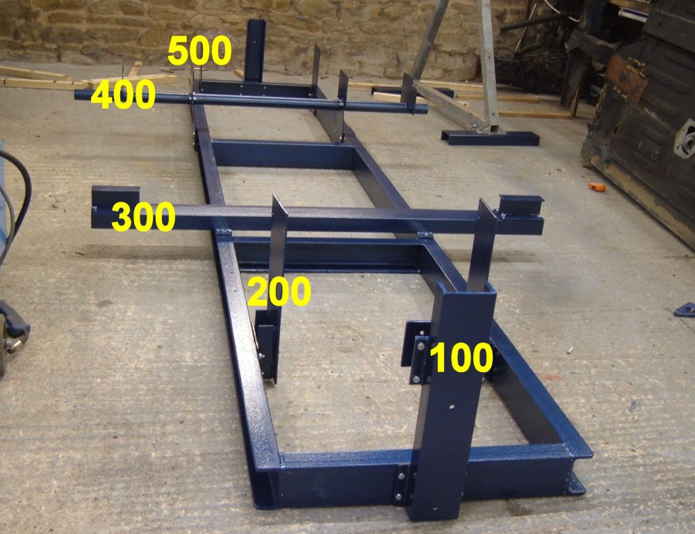
To avoid confusion I'm going to number the different attachment points on the chassis:
100: Gearbox mountings on the front crossmember.
200: Front suspension mountings
300: Lower surface of floor panel
400: Rear suspension mountings
500: Rear bumper mountings
So if a hole position has a co-ordinate 204, then it'll be one of the mounting holes for the front suspension.
Co-ordinates on the left side of the jig have odd numbers, and are incremented by 1 to make numbers on the right side. Pretty well everything is symmetrical left to right.
All co-ordinates refer to the center of the bolt holes on the face of the plate that bolts to the chassis. The photos often show the holes from the other side of the plate, but that's just for illustration.
The co-ordinate system
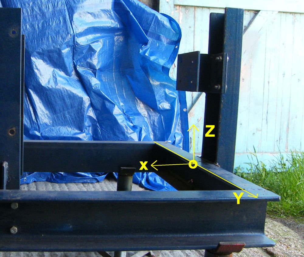
Here's a shot of the front of the chassis jig.
X: Starts at the rear of the front cross brace and is positive to the rear.
Y: Starts at the centre line of the jig and is positive to the right.
Z: Starts at the top face of the jig and is positive upwards.
So that point with the yellow zero would have the (x, y, z) co-ordinates of (0, 0, 0). There's a table at the bottom of the page with the co-ordinates for all the mounting points.
The standard section
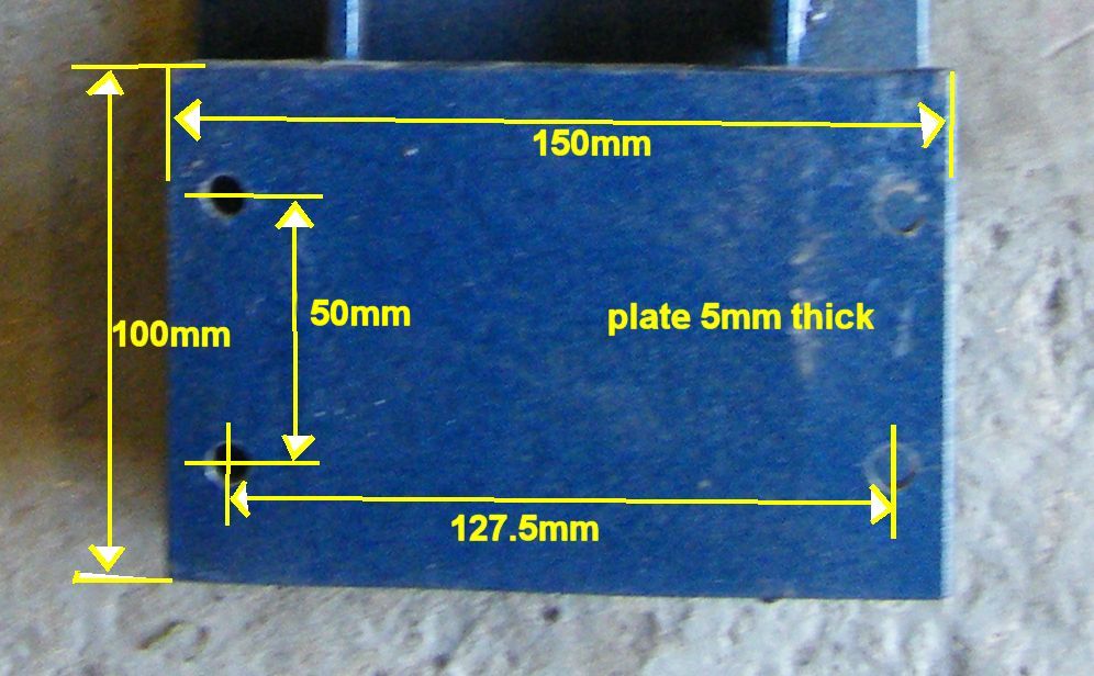
There are missing dimensions throughout this page. They aren't necessary because I used standard mounting hole positions for all the parts that bolt to the jig. You'll need to know these to make sense of the jig.
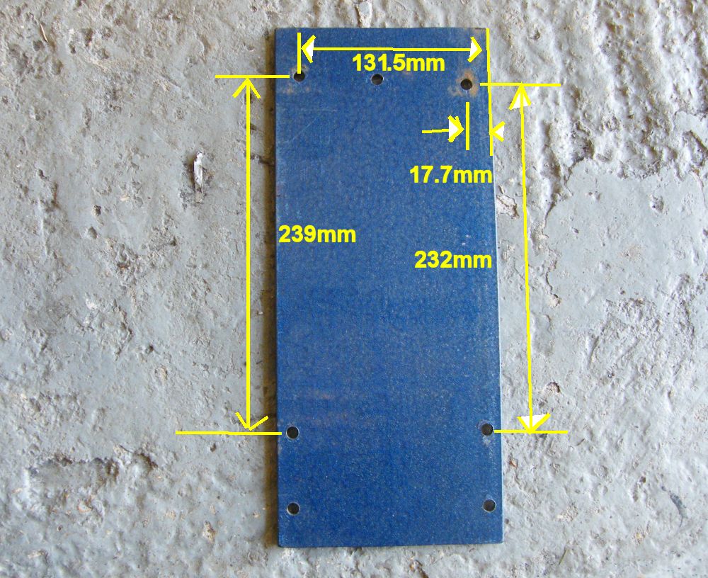
Here's my standard attachment plate. The holes are an equal distance from the center of the plate.
The C section I used is 100mm tall and 50mm wide. Holes drilled in that to take the attachments reflect about the center of the C section.
All of the plate used in the jig was cut from 5mm thick 150mm wide plate.
Front crossmember attachment
The photo shows the construction of the attachment for the front crossmember, and the location of 3 out of 4 of the mounting holes.
This attachment is bolted through the gearbox mounting holes on 4 speed Renault 4s. I don't have dimensions for the 3 speed crossmember (yet).
The mounting positions in the table at the bottom of the page have been measured from the rear face of the front cross brace in
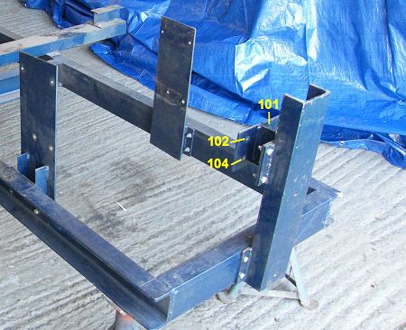
Here's how the front crossmember was constructed. All the plates are standard size 150mm x 100mm, and all of the holes are mirrored about the centre of the plates.
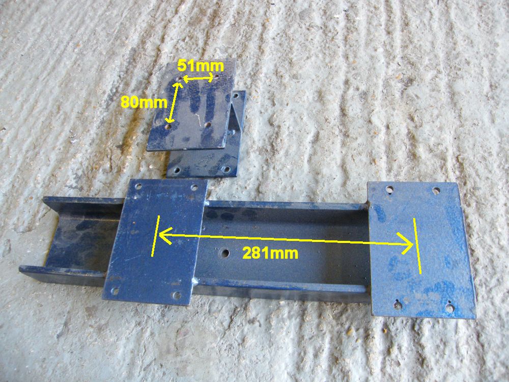
The 'I' section that bolts between the vertical part and the gearbox crossmember measures 72.6mm deep between the outside faces.
Front suspension attachment
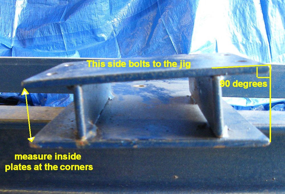
This is quite a tricky part - it slopes inwards towards the top, and inwards towards the front of the chassis.
The table at the bottom of the page gives the co-ordinates in the system described above, but the part doesn't align with the co-ordinate system so for making the part use the dimensions in the photos below.
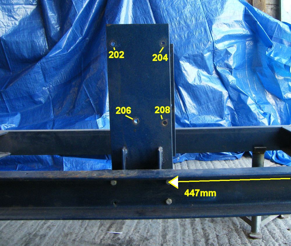
447mm is the distance from the zero point to the center of the front bolts holding the front suspension attachment to the chassis jig.
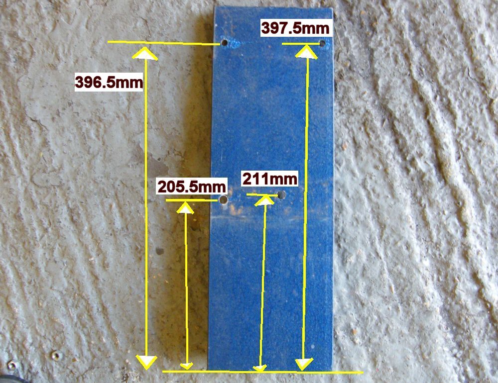
Here's the reverse side of the front suspension mounting plate showing the vertical dimensions. The bottom of the plate is level with the bottom of the chassis jig (and 100mm below the top of the chassis jig.
And some fore-aft dimensions. This is the reverse side of the right hand front suspension mounting attachment.
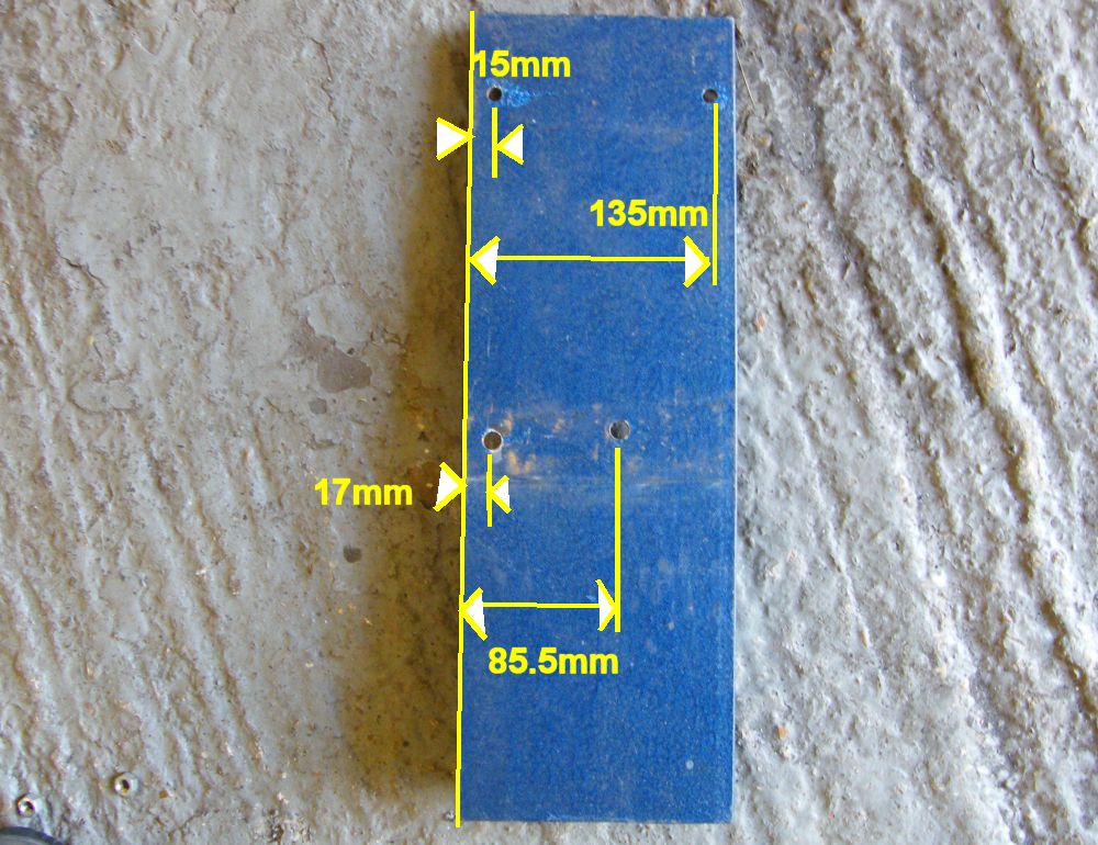
The front of the chassis tapers in towards the top and towards the front. So the mounting plate needed to mounted in an odd position.
The photo shows the distance between the standard inner plate that bolts to the jig, and the outer plate that bolts to the front suspension mountings.
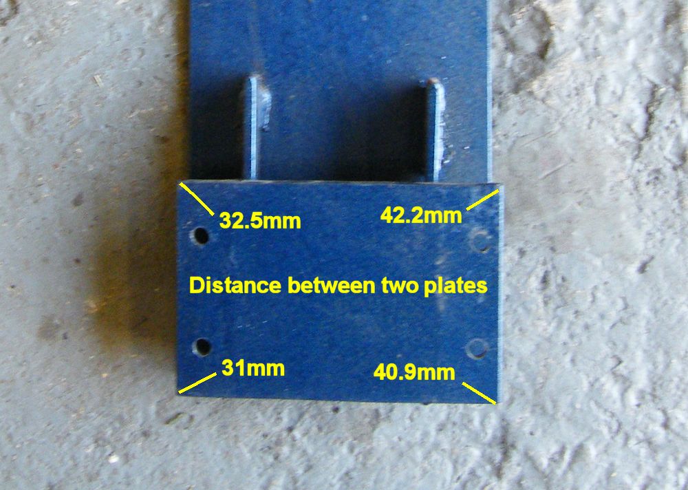
Here's a little more information - to help make sense of it all. The picture is incorrect - the left hand faces line up not the right hand faces in the photo.
Though it would be much easier to make the jig, make the plates that bolt to the front suspension, then make something to go between. Too much scope for inaccuracy in making the part exactly as it says here.
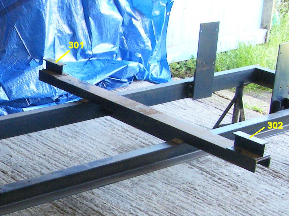
Floor support
The chassis jig is parallel with the chassis floor panel, so the floor support can be positioned wherever work needs doing on the floor.
The co-ordinates refer to the top face of the floor support.
There aren't any holes to bolt the floor support to the floor. I used small G clamps, but it would have been easier if I'd left a flat clamping face at the edge of the jig.
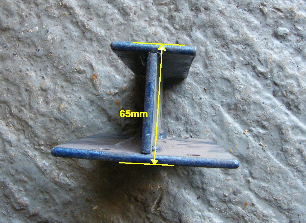
The dimensions of the floor support are unimportant. It is constructed from C section channel with two 5mm flanges underneath with bolt holes 655mm apart to connect it to the jig, and an I section bolted on at each end to support the edge of the floor.
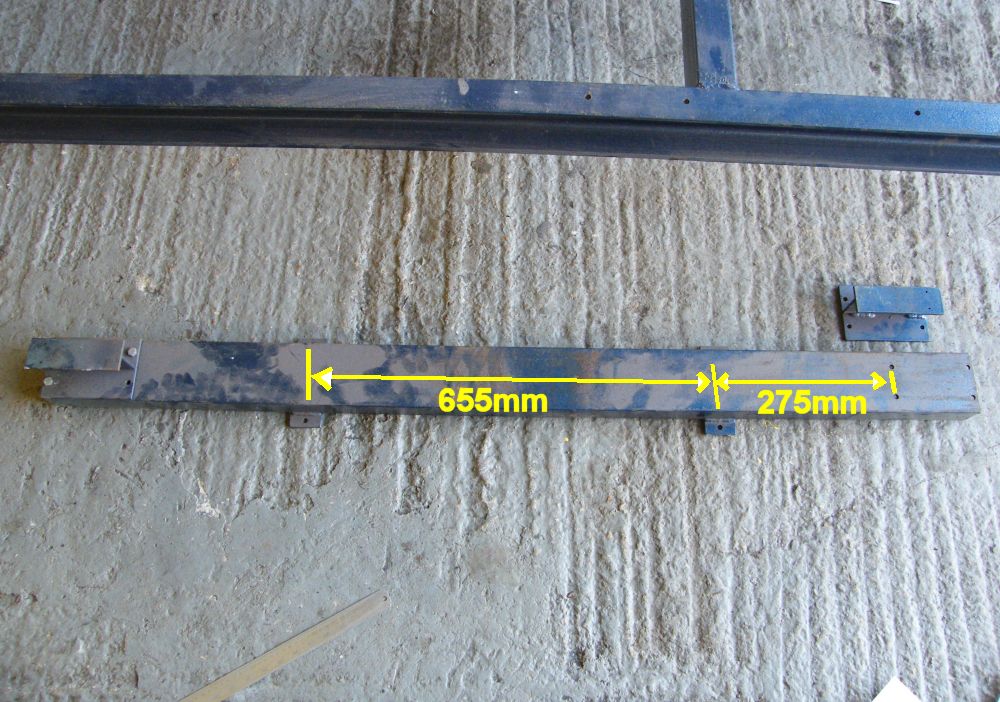
The height of the I section at the end of the floor support is 65mm.
The total distance between the top of the I beam (where it meets the floor) and the top face of the chassis jig is 120mm. Note> The workshop manual suggests the distance should be 125mm rather than 120mm.
My rear suspension jig bolts on to the chassis jig. Dimensions for that are included on the rear suspension jig page.
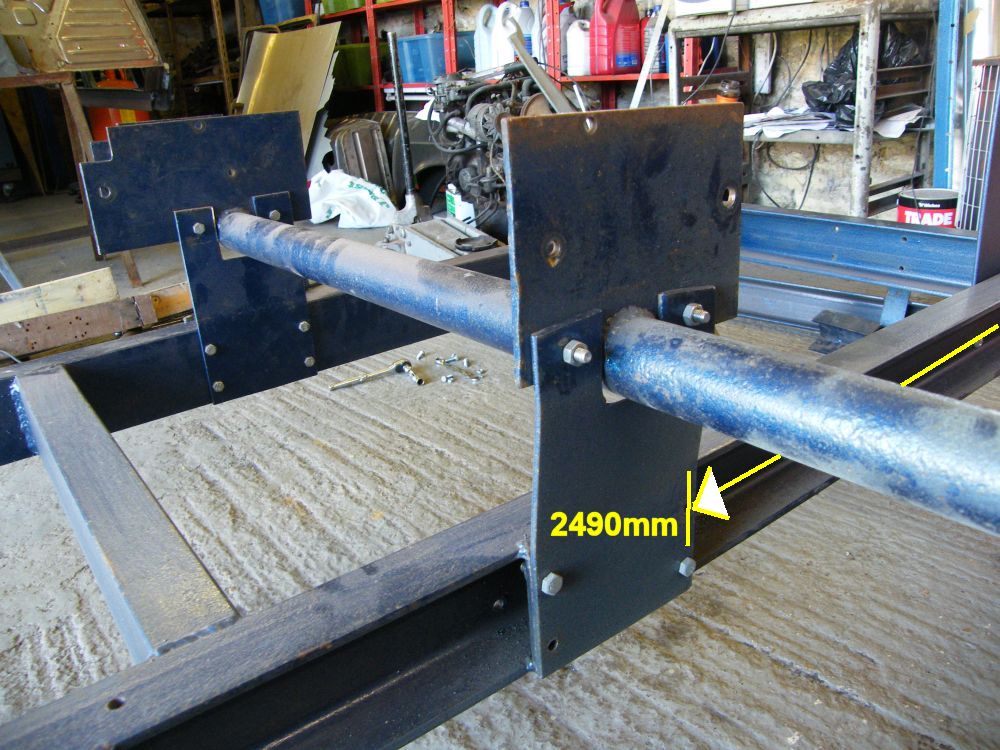
The jig is designed to fit either side of the rear suspension mounts. The pieces joining the suspension jig to the chassis are also reversible. In the photo it is set up to bolt to the left side of the chassis. To bolt the jig to the right side of the chassis currently bolted to the inside of the jig on the right side would be bolted to the inside of the jig on the left side.
2490mm is the distance between the rear face of the front cross member and the front mounting bolts for the rear suspension.
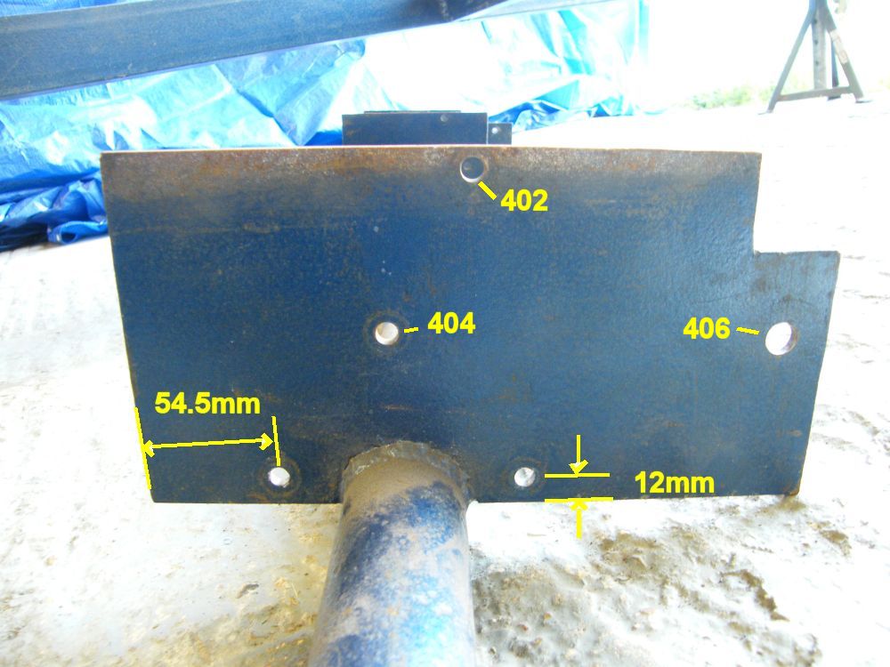
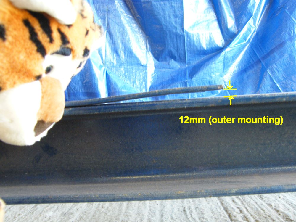
The suspension jig is parallel to the chassis jig, so both of the holes mounting the suspension jig to the chassis jig are centered 12mm from the bottom of the suspension jig plate.
The location of the hole to the left can be related to the suspension mounting holes using dimensions from the suspension jig page.
The distance between the holes was before the plate was bent. This plate had two bends to make the top pair of holes 7mm offset.
The top two holes are 99mm apart and are an equal distance from the center of the plate.
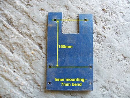
The outer mountings has a 12mm bend rather than the 7mm bend of the inner mounting. The dimensions between the lower and upper bolt holes should be 150.5mm to compensate for the bend.
These bends rely on my chassis jig being 56mm wide (including the extra bit I welded on for the rear suspension)
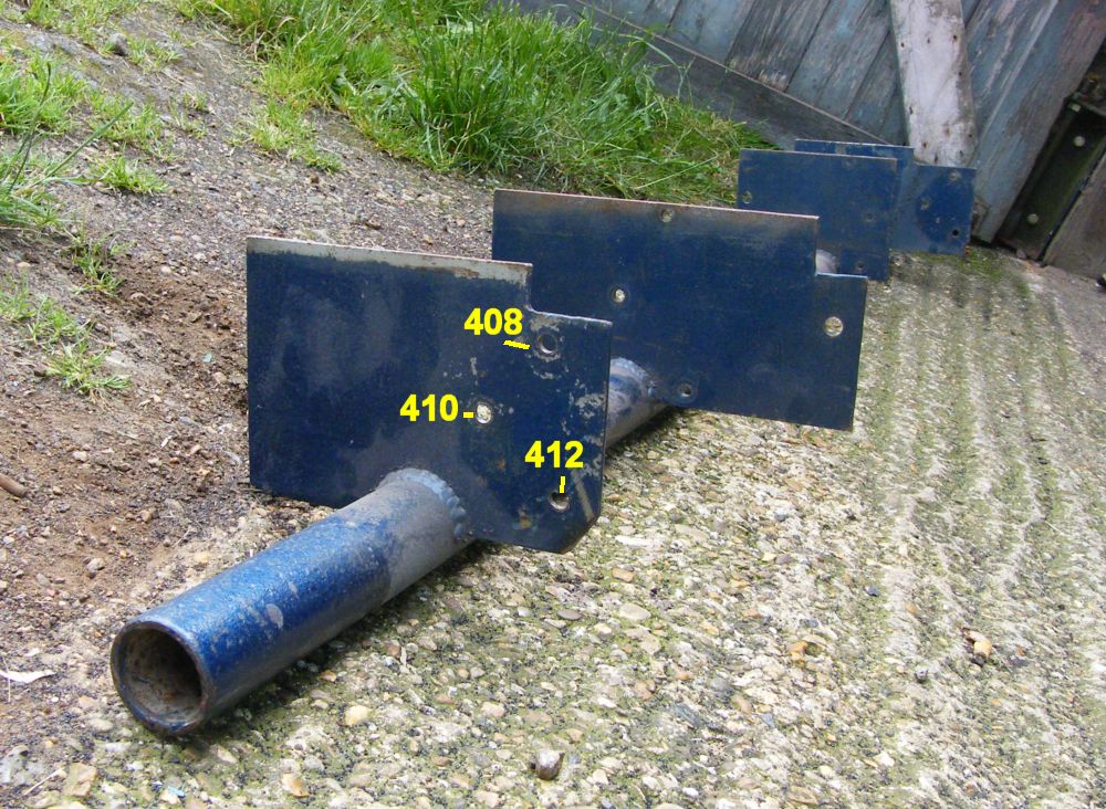
A photo of the rear suspension jig showing co-ordinates of the outer mounting holes.
Two plates support the rear bumper mountings. The distance between the inner faces of the chassis jig is roughly the same as the distance between the rear chassis legs (It was meant to be exactly the same). So these jig sections are flat plates.
I would recommend making a cross brace to fit between the two plates to support the rear of the chassis laterally. Otherwise the rear chassis rails tend to pull outwards when welding the inner rear suspension mountings.
Again you have the distance from the rear face of the front cross brace and the front mounting hole.
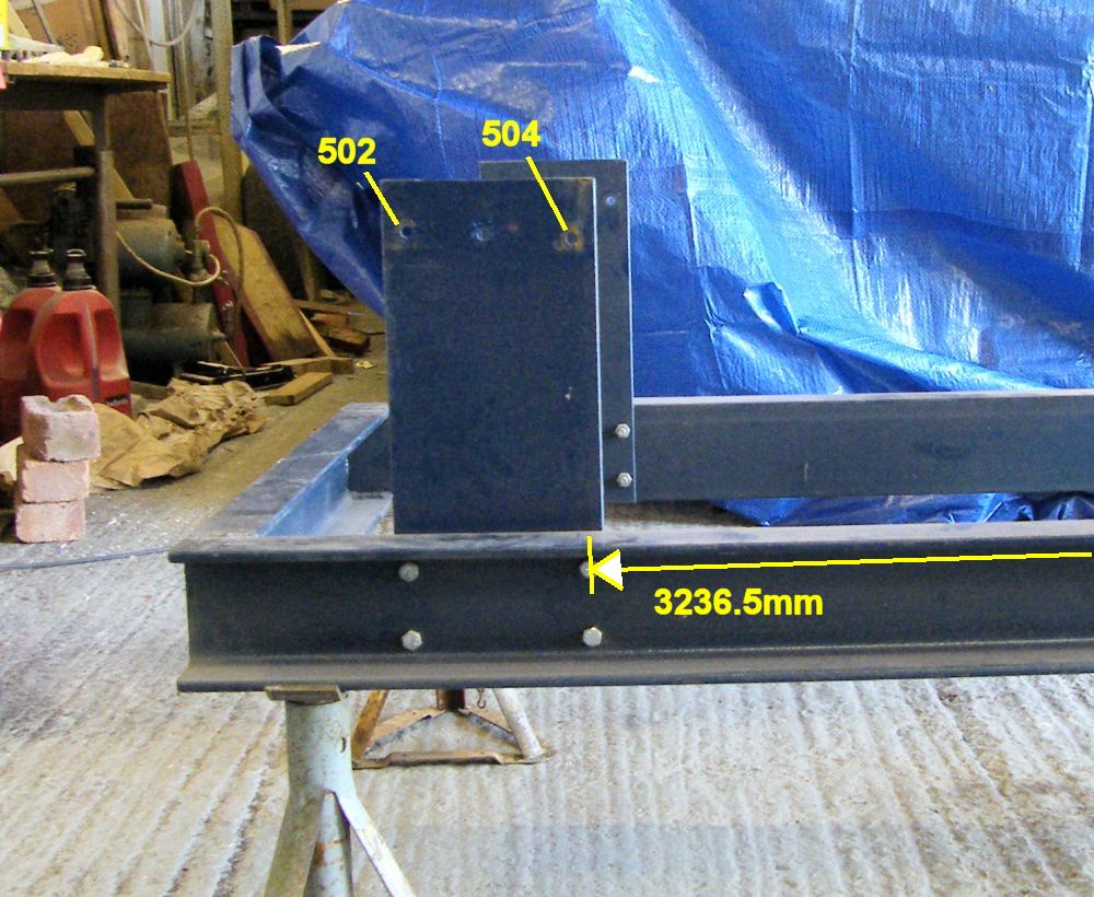
Here are the dimensions for the rear bumper mounting. As always it looks like dimensions are missing - that's the standard hole spacing at the bottom (see towards the top of the page for the dimensions).
Notes
1.For building the jig - if you have a chassis that is just about straight to start with then use that to help position the parts. Only work exactly to these dimensions if your chassis has been crashed or rusted so badly that the mounting points are in the wrong place.
Renault didn't use these points when building the car - they had their own jigging points on the major panels, so there is tolerance between cars.
2.I made the chassis jig from C section channel. It's handy for bolting bits on, but it isn't stiff. The jig needs to be supported completely level to avoid twist.
If I were to make the jig again I'd use box section. This would be much stiffer (though still the level would need to be checked for important repairs).
Co-ordinates
Co-ordinate |
x |
y |
z |
notes |
102 |
20.6 |
40.1 |
256.5 |
All co-ordinates are in mm measured from the reference point at the front of the jig shown in the second photo on the page. The rear suspension jig does not mirror about the centre of the car. See the suspension jig for dimensions for the left side. The co-ordinates here are for the jig fitted to the left side of the chassis as in the photos above. |
104 |
20.6 |
40.1 |
205.5 |
|
202 |
575 |
251.4 |
297.5 |
|
204 |
455 |
239.7 |
296.5 |
|
206 |
525.5 |
250.6 |
111 |
|
208 |
457 |
232.7 |
105.5 |
|
302 |
na |
na |
120.5 |
|
402 |
2978 |
302.5 |
246 |
|
404 |
3009 |
302.5 |
185 |
|
406 |
2857 |
302.5 |
183 |
|
408 |
2937 |
601.5 |
217 |
|
410 |
2970 |
601.5 |
177 |
|
412 |
2927 |
601.5 |
141 |
|
502 |
3357 |
302.5 |
214 |
|
504 |
3243 |
302.5 |
207 |
Workshop manual dimensions
Click the image on the left for a full size scan of the dimensions page from the MR-61 workshop manual. It's about 2Mb in size so save it and print it out. It's not all that clear.
You can use this to cross-reference my co-ordinates, and make corrections to make the jig dimensions closer to what the factory intended. My co-ordinates were based on a real chassis and are slightly different in places.
You can see the chassis jig in action on the Gordini project pages.
Back to Tech Tips