Chassis Jig and Roller
The R4 chassis I find seem to need more and more work these days.
Bluebell needs the front middle section of the floor completely removing, and the Gordini project needs new floors and front and rear ends. Time to build a chassis jig.
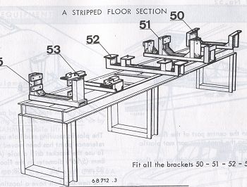
Flipping through the 1972 factory workshop manual I found a picture of a chassis jig and decided it would be a good idea to build one of my own.
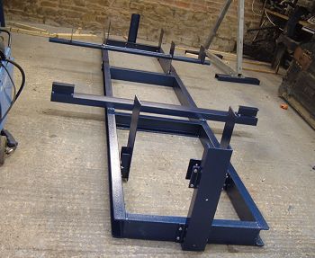
Here's my version of the jig. It's made from C section channel like the one in the workshop manual (the construction is covered in more detail on the welding website.
My version is much simpler than the factory jig, and picks up on the front and rear suspension mountings, the floor, the front cross member and the rear bumper mountings.
I didn't think it through terribly well. I copied the factory C section construction for the jig frame and it doesn't have very much torsional stiffness. Turns out the factory jig is designed to be bolted to the floor.
No matter - the R4 chassis doesn't have any torsional stiffness once the floor has been removed, so the chassis jig is plenty stiff enough to hold things in the right place.
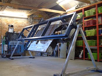
Here's the jig in action. I've mounted the ends on A frames to lift the chassis to a nice working height and allow it to spin around to allow access to all the tricky bits.
The jig makes working on the chassis so much easier than working on the ground. The couple of weeks spent making it were well spent. It's possible to remove each attachment from the jig individually to allow access for local repairs to the chassis.
Dimensions for the chassis jig can be found in the chassis jig dimensions page. You can see the chassis jig in action on the Gordini project pages.
If you are viewing the restoration pages here's the jig in action:
Next > Inner rear suspension mounting
Back to Tech Tips


