Renault 5 Mk1 Rear Suspension Mounting Repair
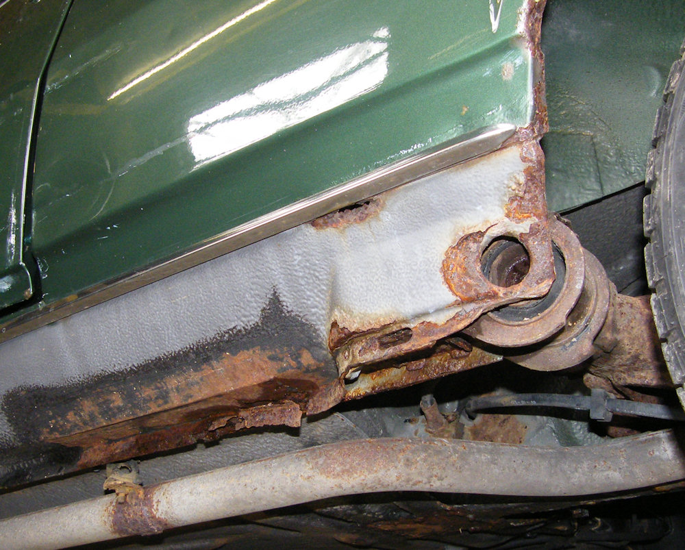
They reckon rust in the outer rear suspension mounting is the thing to watch for in the Renault 5 Mk1. This one looks a bit tatty around the edges and the rear of the sill has been patched in the past.
The spot welded joint at the bottom of the sill has expanded with rust so there's definitely some rot that needs sorting out in there. Also a screwdriver will go through in places.
My top tip for repairing cars - take the wheels off and jet wash the underneath and arches. Makes the car much more pleasant to work on without the dirt falling into your eyes, and you can see what needs doing without the mud. This one turned out to be nice underneath.
The rear suspension is a pain to remove on the Renault 5. The torsion bars pass through a hole in the rear chassis members and have to be removed before the suspension arms can come off. Haynes helpfully suggest giving the torsion bars a light tap with a hammer which might have worked 30 years ago but less so now they have seized in place.
I ended up unbolting the rear suspension and let it dangle from the rear chassis members where it annoyingly restricts access. Even after a really good jet wash there's still mud in the mounting.
The really weird thing is the sealing in the back of the sill. That black and yellow thing is a rubber edge seal which was attached to the outer sill before it was welded in place. There was no seam sealer to keep water out of the sill.

This is the first time I've tackled the Renault 5 rear suspension mounting, and I've not seen a lot of information on the internet about the repair, so the approach was to cut that patch off the sill and have a look inside.
The diagonal part that looks rusty in the center of the photo is the outer reinforcement for the suspension mount.
Forward of my inspection hole the sill looks OK - which is surprising as there is also has a hole in the front wheelarch. I might have a look at that before replacing the sill at the rear just in case I need a complete sill.

A bit more angle grinding needed - the inspection hole was extended all the way to the rear of the sill. I took a pattern from the complicated looking bit at the back of the sill before cutting it off.
Of course a bigger inspection hole just lets you see more rust, so the hole was extended past the little hole in the top of the sill.

Finally we can see the structure. The inner sill is a flat piece of sheet that folds outwards at the top and then upwards to form the top sill seam.
The suspension mounting itself is a U shaped bracket with a couple of spacers inside fastened to the rear of the inner sill.
Most of the rusty coloured stuff in the photo is the outer reinforcement for the mounting which tapers back to the inner sill and has a jacking point fixed beneath. The outer reinforcement shouldn't have the big hole in it - that's where the silly rubber edge seal sat. It's rusty at the bottom too so needs to come off.

The outer reinforcement was cut off in an odd way - that was just to provide access for the angle grinder without having to remove more bodywork.
Removing the outer reinforcement exposed some holes in the inner sill. They were expected - the bottom seam of the sill was completely rotten.
More angle grinding....

With the bottom of the inner sill removed we're back to real metal but the car looks a state.
There was also a small hole right at the top of the inner sill which was cut out with an air grinder and filled with a little patch. I wanted to keep as much metal around the rear suspension bracket as possible - if I remove it I'll need a jig to get it back in the right spot.

Finally a bit of welding after all this angle grinding.
The metalwork for the inner sill and outer reinforcement is 1.2mm thick which makes it reasonably easy to weld, but access is poor under there which makes it a hassle again. Proper prep and clean metal is a must. Don't forget to wear welding gloves to avoid hand cancer from the UV - TIG ones are fine for car bodywork if you find the MIG ones a bit thick.
mig-welding.co.uk has tutorials aimed at doing just this sort of thing if you have the necessary rust but are new to welding, but make sure you get a decent welder - makes all the difference for decent results in positional welding in an uncomfortable position when you can't quite see what you are doing (welding cars).

With access to the inside face of the rear suspension mount limited by the suspension dangling in the wheelarch I'm aiming to do as much welding as possible from the outer side.
The repair to the bottom of the inner sill was seam welded to the existing panel, and then plug welded to the floor and finally the suspension mounting bracket. the welds at the bottom will need to be ground flush to give a flat surface for the next section.

Next job was the outer reinforcement. I kept the bit that was cut out, but there's not enough of it left to be certain about the construction.
A bit of guess work would be required.

The way to figure this sort of thing out is making a template from card. Card bends like metal but is cheaper and much easier to cut and bend.
The template in the photo was the second attempt. Once I was happy with it the dimensions were scribed onto a piece of steel which was folded to shape. Then hammered a lot to make it fit.

Here's my interpretation of the outer reinforcement. It's butt welded at the top and then plug welded where it would have originally been spot welded.
Those blue lines at the front are markings for an attempt at replicating the swage line. We're going for a proper original job here.

Before the outer sill can go back on there's some messing about to be done inside the wheelarch. removing some of the anti-stonechip primer revealed solid metal. It's only gone at the edges.
Unfortunately the rust has spread under the corner of the seatbelt mounting. It's held on by about 5 spot welds which were drilled with a spot weld drill bit for access to the panel behind.

With the seatbelt mounting removed there was only a small triangle of wheelarch that needed to be cut out.
I've been pondering about what to do with that rear suspension mounting. I don't want to have to remove the rear suspension every time I jet wash the car, and now seemed the time to do something. I've decided to close it off and drill a drain hole at the bottom to connect it to the sill cavity.

That's more like it!
Mud collecting inside the suspension mount itself is easy to remove with the jet washer, but more than likely some sort of wheelarch liner will appear later on to stop the mud getting that far.

Back to the inner wheelarch. The repair is just a case of welding in a little triangle of 0.8mm sheet and repairing the holes where I drilled too far removing the seatbelt mounting.
The original seatbelt mounting is in good condition and was plug welded back on after the welds had been ground back towards the surrounding metal.

A bit of Rustoleum finishes off the job. I'll go about it with seam sealer and anti-stone chip paint, then colour just as the factory did it.
All that's left now is the crusty metal at the front of the wheelarch. Both the outer and inner skins have gone, but only in a very localised area.

Next cutting out the rusty bits from the inner and outer wheelarch. There wasn't that much rust but access for the angle grinder was a bit limited so a good sized section came out.
You can see inside the car through that hole.

Welding the new part in place was a complete pain. Access is poor with the rear suspension still filling up the wheelarch and the torch had to be at a bad angle to see past the shroud while welding. Not ideal when when trying to butt weld 0.8mm sheet.

Finally there's no rust in the rear suspension mounting area, but we're still running short on metal - the front part of the outer skin of the wheelarch and much of the outer sill are still missing.

That's better - rusty again!
The old sill is just on to check the position of the inner wheelarch repair. It's too rusty to go back on. I was in half a mind to replace the whole outer sill, but that's a bit fiddly around the door pillars and rear section. The original sill looks good apart from the part I've cut out so I decided on a repair.

As always the repair started life as a cardboard template - makes it so much easier to figure out shapes and dimensions.
In this case the repair will be made from 2 sections - there's an additional infill section where the sill curves outwards towards the mount cover.

Once the template was completed the shape was transferred onto sheet steel. The outer sill seems quite thick. I've gone for 1.2mm but it's possible it should be 1mm.
The suspension mount cover is a fiddly bit to reproduce. There's a lot of detailed swaging around the hole for rear torsion bar removal.

Working out how to reproduce the swages was fun. The bends around the edges of the section went in first then were hammered flat again in the region of the torsion bar access hole as the bends follow the hole around.
The hole itself was cut a few sizes too small with a 1/2 inch hole saw, then the swage pressed in using a thick tube as a former. A solid bar with a taper was hammered through the hole using a big hammer. Finally the swage below the hole was knocked in using a hammer and dolly. The hole turned out quite well but with larger bend radiuses than the original.

The rest of the bends were folded using the edge of a steel table.
The photo shows the insert used to complete the repair section. The insert includes the bends in that area so the joins are flat to flat so easier to control. There's spare metal in the flange that will need to be trimmed off.
Comparing the width of the bottom of the insert with the flat piece of steel used to make the sill repair shows how much the metal at the bottom was stretched to make the original pressing - I've had to add a further inch!

Finally the welds were ground just to the surface of the surrounding steel and finished off with an 80 grit disc. There are plenty of pits in the surface but hopefully a thick enough coat of anti-stonechip primer will hide them.
The repair section was made a little large and trimmed to fit. There's about 0.5mm gap all around where it will be butt welded. This will close up when welding.

Before the sill can go back on the end needed sealing off. The arrangement around here was the cause of the rot problem to start with so I've redesigned a little.
The blanking plate will be welded to the inner and outer sill and seam sealed all around, and it sits just above the rear of the jacking point stopping that from becoming a rot trap.
The hole in the jacking point has been extended so the only horizontal surface for mud to sit on is the very rear edge of the jacking point. I'm not quite sure why I refitted the jacking point, and as that rear edge doesn't do a great deal structurally I wonder if it might become the casualty of an angle grinder sometime soon so I can get rid of the mud trap completely.

The repair section was tacked in place, left to cool, tacked some more, then the tacks ground down to make them easier to weld over.
The welding was done in short sections about an inch long, one at the back, one in the middle and one at the front before being allowed to cool. The process was repeated until the whole panel was welded in.
The bottom edge was held loosely with a clamp and the rear wasn't welded until the seam was finished so the metal had somewhere to move when it got hot.
All of this helped to reduce distortion.

Finally the bottom seam, jacking point, sill blank, and rear wheelarch could be connected using plug welds.
I've ground the seam welds down with a flap disc only as far as they need to be ground down. The bit in the photo will be covered by the bottom of the rear wing, but there's always a bit of distortion and filler will be needed, so there's no point risking thinning the metal around the weld to make it look pretty if it's going to be filled over anyway.

The front corner of the rear wheelarch was the last part to go back on. It's the normal plan - butt weld it where the panel was cut, then plug weld where there were originally spot welds.

The rear body side is fairly flat and unsupported so there's a fair chance of heat distortion when welding a repair section along it's length - the body side could easily end up with huge dents.
Welding the repair section to the side panel before fastening it to the surrounding structure means the repair section distorts instead of the main panel. It's pulled away from the sill and the bottom edge has become very wavy.

It's quite easy to remove the distortion in the repair section - the metal could be pushed against the sill for plug welding then any distortion knocked out with a hammer against the sill.

A bit of paint doesn't quite finish off the job - it'll need a bit of filler to straighten out the distortion I do have, and a whole load of seam sealing inside the wheelarch to help reduce the chances of rust in the future.
The repair took about 8 days in total, though they weren't hard working days. Enough to make me think twice about doing the other side - that looks like it has just started to go at the bottom but will probably last another few years. Maybe I'll just cut a small hole and have a look inside....

Last update 21 June 2011
Next: Damper tower and all the other rear wheelarch issues
Back to: Renault 5 Restoration